TEID 2
Bearer Building and Tunnel Timing
from ; http://lteuniversity.com/get_trained/expert_opinion1/b/donhanley/archive/2012/01/30/bearer-building-and-tunnel-timing.aspx
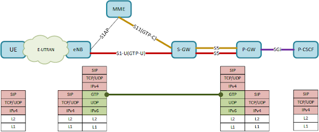
By now, you should be familiar with the concept of an EPS bearer, which transports user traffic between the User Equipment (UE) and the PDN Gateway (P-GW) in LTE networks. If you’ve taken just about any Award Solutions course on LTE, you’ve learned that an EPS bearer is comprised of 3 parts: the Data Radio Bearer (DRB) over the air interface between the UE and the evolved Node B (eNB); the S1-U bearer between the eNB and the Serving Gateway (S-GW); and the S5 bearer between the S-GW and the P-GW.
You will also recall that the S1-U and S5 bearers make use of GPRS Tunneling Protocol (GTP) to identify the individual bearers connecting two nodes. Since each eNB, S-GW and P-GW may be supporting hundreds of active bearers, the GTP Tunnel Endpoint Identifiers (TEIDs) assigned to each bearer allows each node to determine which specific bearer a particular packet belongs to.
But did you realize that this neat little description of an EPS bearer, which appears in a dozen different courses, is not entirely accurate?
Half-Baked Bearers
The following illustration shows the traditional view of an EPS bearer, with three pipes representing the individual bearers carrying packets between the nodes.

The reality is that the S1-U and S5 bearers are actually pairs of one-way tunnels, not the two-way pipes we traditionally draw. Each end of the bearer is identified by a TEID assigned by the node at the far end of the GTP tunnel; two TEIDs are needed to create each of these bearers, one for each end. As soon as a node learns the TEID of the other end of the tunnel, it can start sending data in that direction.
One two-way pipe, or two one-way pipes: what’s the difference? In reality, not much, except in one place. Let’s look at a typical EPS bearer setup sequence.
Bearer Building
A typical (albeit simplified) bearer establishment sequence is shown here. Bearers are automatically set up as part of the network attach procedure, and may be added at any time to support additional services or connections for the UE. Although bearers do not pass through the MME, it is responsible for coordinating the effort.

When the S-GW receives the Create Session Request from the MME, it assigns a TEID for its end of the S5 bearer, and forwards it to the P-GW. As soon as the P-GW processes the message, at point A in the message flow, it knows how to send packets to the S-GW; the downlink half of the S5 bearer has been created. In turn, the P-GW assigns a TEID for its end of the S5 bearer, and sends it to the S-GW in the Create Session Response message. At point B, the uplink half of the S5 bearer is in place, and that portion of the EPS bearer establishment is done.
The S-GW then allocates a TEID for its end of the S1-U bearer and passes it back to the MME, which forwards it to the eNB; at point C in the message flow, the eNB could start sending packets to the S-GW, if there were any to send. The eNB takes care of defining the DRB portion of the bearer (GTP is not used over the air interface, and so TEIDs are not required); as soon as the UE responds (at point D in the message flow), both directions of the DRB are in place.
Note that, at this moment, the entire uplink path between the UE and the P-GW is in place. If the UE has data in its buffers (which would not be unusual), packets can start flowing in the uplink direction, even though the EPS bearer is not completely defined.
To finish off the process, the eNB allocates a TEID for its end of the S1-U bearer and sends it up to the MME to be passed along to the S-GW. Once the S-GW receives the Modify Bearer Request from the MME (point E in the flow), the last piece of the puzzle is in place, and the EPS bearer is complete, ready to transport traffic in both directions.
Tunnel Timing
The two directions of the DRB are defined simultaneously as part of the RRC signaling between the eNB and the UE, while the two halves of the S5 bearer are typically set up within 20 milliseconds of each other, depending on the other functions the P-GW has to take care of (such as IP address assignment). However, there is a perceptible gap between the time the uplink half of the complete EPS bearer is ready, and the time the downlink half can start carrying traffic, because of how (and when) the S1-U bearer is configured.
To be fair, we’re not talking a lot of elapsed time here; depending on how long it takes to set up the DRB and how far the eNB, the MME and the S-GW are from each other, it may take between 10 mS and 100 mS to complete the S1-U setup. That may not sound like much, but it can cause some headaches for the user.
Suppose this particular bearer is being established because the user started an application on his device, such as launching a web browser. The first message to set up the web session between the browser and the server can be sent as soon as the uplink path is ready, at point C in the flow. The response, however, can’t reach the UE until the downlink path is in place, at point E. If the response reaches the S-GW before it learns the TEID from the eNB, the response may be discarded, forcing the application to time out and try again. The result is a delay in launching the service, and a slightly unhappy customer.
In the vast majority of cases, everything is ready by the time the server responds, and the delay between the setup of the uplink and downlink bearer paths is of no consequence. Every now and then, however, it can interfere with the startup of the user’s service. If you’re involved with LTE network troubleshooting, just keep this in the back of your mind.
Can you specifiy which GTP-TEID you mean here ? GTP-C TEID or GTP-U TEID ?
If you asked for GTP-U TEID, then there has to be a one to one mapping between a GTP-U TEID and the EPS bearer at different end points like eNodeB, S-GW and PDN-GW, across their supported interfaces on the data flow path.
If it is a GTP-C TEID, then it is interpreted differently across different interfaces
1. On S11, there has to be only one pair of GTP-C TEID (one on MME and the other on S-GW) for one UE. This must be shared for all the control messages' related operations related to this UE.
2. On S5/S8, the GTP-C TEID has to be unique per PDN connection. And this has to be shared among all the EPS bearers which use this PDN connection. (However the spec doesn't mention anything about the UE here).
Some more interfaces like S3, S10, S16 which are dependent on LTE, See spec 29.274 section 4.1 & 3GPP 29.281 1. On S11, there has to be only one pair of GTP-C TEID (one on MME and the other on S-GW) for one UE. This must be shared for all the control messages' related operations related to this UE.
2. On S5/S8, the GTP-C TEID has to be unique per PDN connection. And this has to be shared among all the EPS bearers which use this PDN connection. (However the spec doesn't mention anything about the UE here).
f or multiple Bearer?
It has to be unique across all bearers for that end point pair(eNB-SGW pair OR SGW-PGW pair). It is the TEID that uniquely identifies the bearers.
The separate tunnels are identified by a TEID (Tunnel Endpoint Identifier) in the GTP-U messages, which should be a dynamically allocated random number. If this random number is of cryptographic quality, then it will provide a measure of security against certain attacks. Only GTP version 0 used TIED is not random

Comments
Post a Comment